
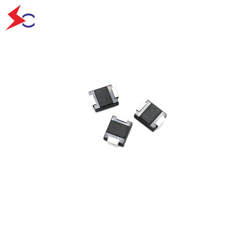
1、Analysis of Overvoltage Threats Facing Automotive Electronics
1. Load Dump:Sudden disconnection of the battery during alternator operation generates a high-energy pulse with an amplitude of 40–120 V and a duration of hundreds of milliseconds.
2.Load Dump:Instantaneous disconnection of a high-power load generates a transient voltage of 60–150 V.
3.Reverse Battery:Reverse battery connection causes reverse voltage from -12V to -24V.
4.Cranking Transients:When the motor is started, the voltage drops sharply to 4–6 V and then rebounds to 40–50 V.
(ESD):±15 kV electrostatic pulses generated by human contact.
2、Advantages of TVS Diodes in Automotive Protection Circuits
Compared to traditional Varistors and Ceramic Gas Discharge Tubes, TVS diodes offer advantages in automotive applications:
1.Response Speed:Picosecond-level response, far surpassing the microsecond-level delay of Gas Discharge Tubes.
Clamping Accuracy:Precise avalanche voltage ensures the protected IC remains within the safe zone at all times.
2.Service Life:Lossless mechanism, meeting the 10-15 year lifespan requirement for automobiles.
Temperature Characteristics:-55°C to +175°C wide temperature range meets automotive-grade requirements.
3.Package Dimensions:SMC/DO-214AA and other miniaturized packages are suitable for high-density PCB designs.
3、Typical Automotive Application Circuit Design
3.1 Power Input Terminal Protection Solution
Batteries Positive Terminal → 60A Fuses → TPSMEJ33CA(TVS) → 47μH Inductor → ECU Power Management IC
↓
Chassis Grounding
TVS Breakdown Voltage:36.7V-40.6V
Maximum Clamping Voltage:58.1V@15.7A
Continuous Operating Voltage:33V
3.2 CAN Bus Protection Circuit
CAN_H → 120Ω → TPSMEJ33CA → CAN Controller
↓
GND
CAN_L → 120Ω → TPSMEJ33CA → CAN Controller
↓
GND
3.3 Sensor Interface Protection
Analog signal interfaces for Oxygen Sensor, RPM Sensor, etc.:
Each signal line is connected in parallel with a bidirectional TVS diode to ground.
Add TVS diodes between differential signal lines to achieve common-mode and differential-mode protection.
Forming multi-level protection in conjunction with a π-type filter.
4、Key Parameters Selection Guide
Operating Voltage Selection: Vrwm ≥ 1.2 × Maximum Normal Operating Voltage
12V System: Select 22-24V TVS
24V System: Select 33-36V TVS (This document selects TPSMEJ33CA)
48V Hybrid System: Select 58-70V TVS
Clamping Voltage Calculation:
Vclamp = Vbr + (Ipp × Rd)
Among them: Vbr - Breakdown Voltage, Ipp - Peak Pulse Current,
Rd – Dynamic Resistance.
Energy Withstand Capability Evaluation:
Test pulses 1/2/3a/3b/5a according to ISO 7637-2
Perform load dump testing per ISO 16750-2
5、Vehicle-in-the-loop Test Verification Data
In the ECU module upgrade for a certain vehicle model:
Original solution: Varistor + self-resetting fuse
Current solution: Single TPSMEJ33CA TVS diode
Comparison of Test Results:
Test Items | Approval rate of the original plan | TVS Solution Approval Rate | Improvement Margin |
Load Dump Test | 78% | 100% | +22%
|
ESD Contact Discharge | 85% | 100% | +15% |
Reverse Voltage Test | 72% | 100% | +28% |
Temperature Cycling Test | 88% | 100% | +12% |
6、Installation Design Specifications
Layout Requirements:
TVS distance from protected IC pin < 2 cm
Ground path impedance < 10 mΩ
Avoid vias between the protection device and the protected device.
Thermal Design Considerations:
Transient Power: Pp = Vclamp × Ipp
Continuous Power: 0.4W (Derating required for ambient temperature)
Recommended PCB Copper Thickness: ≥2oz
Wire Harness Design:
Power cables use twisted pairs to minimize loop area
Ground wire cross-sectional area ≥ 2.5 mm²
Shielding layer terminated 360 degrees to chassis ground
7、Compliant Automobile Standard Certification
AEC-Q101 Certification (Automotive-Grade Reliability)
ISO 7637-2 (Conducted Transient Disturbances for Road Vehicles)
ISO 16750-2 (Electrical Environmental Conditions for Road Vehicles)
LV 124 (German Automotive Manufacturers' Electrical Standard)
Conclusion
The TVS (TPSMEJ33CA) diode has become the preferred solution for overvoltage protection in modern automotive electronic systems, thanks to its excellent response characteristics, precise clamping performance and automotive-grade reliability. Through scientific parameter selection and rational circuit design, a complete protection system that meets the requirements of various automotive electronic standards can be established, ensuring the stable operation of vehicle electronic systems throughout their entire life cycle.